Table of Contents
| Name |
Topic |
Date |
Revised |
|
Schematic diagram update |
July 2001 | |
 SB#1
SB#1 |
Honda Engines |
November 1996 |
January 2008 |
|
SB#2 |
Replacing Powerrake Fingers |
November 1996 | |
|
SB#3 |
Schematic Wiring Diagrams |
August 1995 | |
|
SB#4 |
Servicing Honda Engines |
August 1995 | |
|
SB#5 |
Converting Branch Collector Auto-Latch Basket to Manual |
November 1996 | |
|
NOTE:
Most of the above documents are available in two formats, HTML (the normal webpage language)
and PDF (portable document format).
PDF is the preferred format for printing out these forms.
To print or save a document in PDF, click on this icon
next to a form name, and
your PDF reader should do the rest. If you do not have a PDF reader, you can
download Adobe Acrobat Reader
for free from the Adobe website.
 Click here
to download Adobe Acrobat Reader.
Click here
to download Adobe Acrobat Reader.
If you have any problem viewing these documents, please contact us.
|
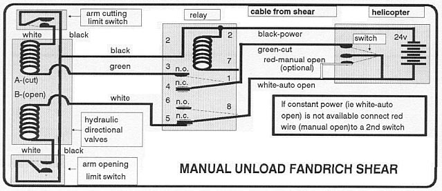
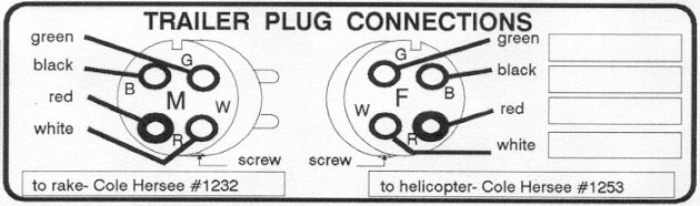
Schematic diagrams
July 2001 Update
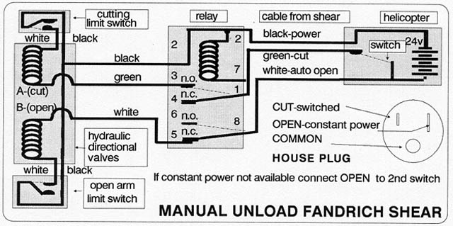
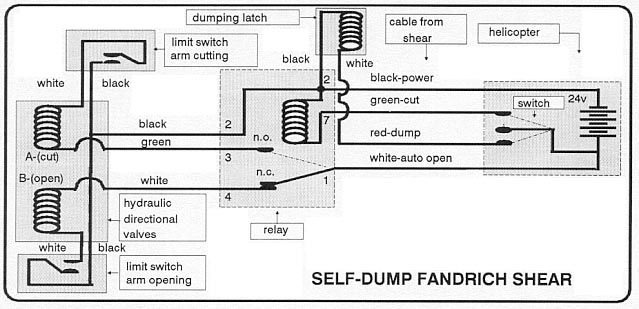
Manual-Unload Shear:
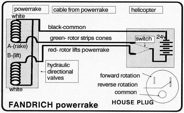
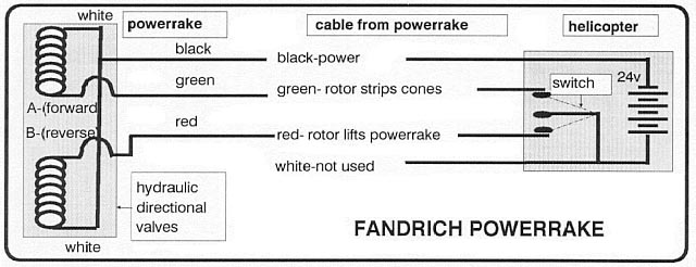
Powerrake:
SB#1: Honda Engines
"SB#1: Honda Engines" is available in PDF format. To view it, please click here.
Click here
to download Adobe Acrobat Reader to view PDF files.
|
SB#2: Replacing Powerrake Fingers
November 1996 Service Bulletin
GENERAL
Due to the nature of the constant flexing that gentle cone harvesting
requires, fingers have a limited life. The plastic fingers have been
designed to be soft enough to minimize damage to the branches yet
stiff enough to be make cone raking efficient. After some time, fingers
will break. Usually the performance of the powerrake will not be
significanly affected when only 2 or 3 fingers are missing.
Suggestions to increase finger life
- Remove any branches that have been caught in the rotors and are
being hit by the fingers. Remove all stuck branches every time
the powerrake comes in to unload.
- Keep the rotors stationary when ferrying. Rotate the rotors only
when needed to strip branches.
- Use the reverse rotation sparingly.
- Minimize the amount of rotor stalling (in congested branches).
- Do not run engine unnecessarily fast. The engine speed at maximum
throttle should be 4000 rpm. (Speed can be read on the tachometer
mounted on the cone side of the engine.)
- Minimize the exposure of fingers to sunlight. If the Fandrich powerrake
is to be stored for more than a few days, store it in the shade or
throw a tarp or covering over the frame to keep the sun out.
SUGGESTIONS FOR CHANGING FINGERS
The fingers come in sets a foot wide with 6 (or 7) fingers per set.
Two sets of fingers make up one row. Three rows of fingers with 2
sets of fingers in each row make up each rotor. A branch deflector
extends all the way across the two sets of fingers.
Here are our suggestions on how to change fingers efficiently. We
mount a 7/16 socket in a slow-speed drill and use the drill to loosen
and tighten the bolts. We use another drill with a 1/4" drill bit
to drill the holes.
- Loosen and remove bolts from one set of fingers (half of a row,
ie 6 or 7 fingers), and all but two (or three) bolts in the other
set (in the same row). These two bolts can be loosened but should
not be removed to keep the other set of fingers and the branch deflector
that extends across the whole row intact.
- Remove only one set of fingers (half of a row).
- Place new set of fingers into slot where old set has been removed,
pounding the set in if necessary.
- Drill 3 or 4 holes (1/4") in the new set as required. (Every second
hole is not used).
- Insert bolts into the new set.
- Remove remaining two bolts from second set of fingers & remove
second set without changing the location of the branch deflector.
- Place new set of fingers into slot where second set has been removed,
drill holes, and insert bolts.
- Turn on nuts and tighten.
- Repeat procedure for the other two rows of fingers.
SB#3: Schematic Wiring Diagrams
August 1995 Service Bulletin
SB#4: Servicing Honda Engines
August 1995 Service Bulletin
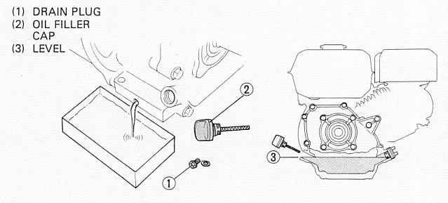
CHANGING OIL
Drain the oil while the engine is still warm to assure rapid and complete draining.
Change oil every 50 Hours with 10W30 oil.
- Remove the oil filter cap, and drain the oil.
- Refill with the recommended oil and check the level.
OIL CAPACITY: 0.6 lit. (0.63 US qt, 0.53 Imp. qt)
AIR CLEANER SERVICE
A dirty air cleaner will restrict the air flow to the carburetor. To prevent carburetor
malfunction, service the air cleaner regularly. Service more frequently when operating
the engine in extremely dusty areas.
 WARNING: Never use gasoline or low flash point solvents for cleaning the air cleaner element.
A fire or explosion could result.
WARNING: Never use gasoline or low flash point solvents for cleaning the air cleaner element.
A fire or explosion could result.
|
|
CAUTION: Never run the engine without the air cleaner. Rapid engine wear may result.
|
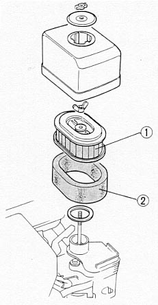
DRY TYPE
- Remove the wing nut and the sir cleaner cover. Remove the elements and separate
them. Carefully check both elements for holes or tears and replace if damaged.
- Foam element: Clean in warm soapy water, rinse and allow to dry thoroughly.
Or clean in high flash-point solvent and allow to dry. Dip the element in clean engine oil
and squeeze out all the excess. The engine will smoke during initial start-up if too much oil
is left in the foam.
- Paper element: Tap the element lightly several times on a hard surface to remove
excess dirt, or blow compressed air through the filter from the inside out. Never try to brush
the dirt off; brushing will force the dirt into the fibres.
1. PAPER ELEMENT
2. FOAM ELEMENT
SB#5: Converting Branch Collector Auto-Latch Basket to Manual
November 1996 Service Bulletin
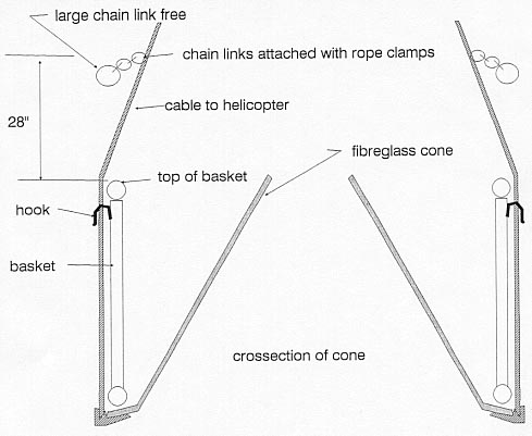
INSTRUCTIONS
- Find three sets of chain links that are attached somewhere on basket.
- Unfasten the three auto-latch cables from cable to helicopter and secure.
- Fasten the three chain links, with large ring free, onto cable with rope clamps.
MANUAL HOOKING OPERATION
When branch collector is lowered onto the ground so that the cable to the helicopter becomes
slack, hook up the large ring over the hook. When the helicopter lifts up, the basket will
move up first to allow the cones and branches to fall out. When the basket is lowered, unhook
the large ring. The basket remains on the cone when the cables become tight again.